Outlines, drawings and execution details are important elements of technical documents.
VCmaster offers various options for transferring and
editing graphics and integrating CAD programs:
- t2W technology: t2W is installed as a printer
driver. Similarly to PDF, t2W directs the print output to VCmaster. With
CAD programs, it has the advantage of being able to transfer data in print mode.
Unlike using the clipboard, line weights and colors are specified. See
also Chapter 3.5.
- VCcopy-Technology: The extended clipboard is the perfect tool for efficiently copying images or graphics. More information:
Chapter 3.6.1.
- OLE technology: CAD programs are integrated via OLE
technology. This technology offers the option of integrating CAD into
VCmaster without buffering. In order to edit, a double-click starts the
CAD application. See also Chapter
3.7.4
- Import interfaces are available in various standard windows formats (wmf, emf, bmp, jpg, png, pcx, gif, tif, and tga).
- Clipboard: This is a Windows standard and is
mentioned for conciseness.
Note: VCmaster is not equipped with an import filter for file formats like: DXF, HPGL, PRN, PLT, DGN, DWG etc.
Those files can be imported using t2W-interface. Call up the respective application or viewer. Select
Print Option and then select
t2W-interface.
The
Sketch-Editor creates simple system sketches. We
favor CAD for more complex details (see
Chapter 3.3.1).
The
Sketch-Editor is not based on CAD-like technology. The graphics are
generated with the aid of special character sets. The corresponding
drawing elements are stringed together and then intelligently linked
with just one mouse-click. Beams, frames, roofs and supports are
sketched with the associated loads and dimensionings.
"Systems" tab
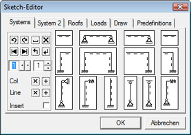 Beams
Beams: After inserting the first field, the cursor is at the location where the next field can be joined.
Frames: After insertion, the cursor is always at the upper right corner. The next frame element can be joined at this location. For multi-story frames, draw the lower floor first, then place the cursor into the top left corner and draw the next floor. Cantilevers can be connected at any point of the frame.
For doing so, the cursor must be at the connection point. The left cantilever is marked to the left of the cursor and the right one is marked to the right.
Supports: The supports must only be defined above the system height. Hinged columns are connected to the frame if the cursor is on the ledger and the downwards drawing direction is selected.
"System 2" tab
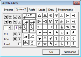 Dimensioning
:
The horizontal dimension can be marked to the left or right. The
vertical dimension can be marked upwards or downwards. The cursor is then at the next possible connection point to continue the dimension chain. The length of the dimension mark must be specified for the height indication. The angle dimensioning writes a symbol to specify the angle.
Bearings and joints: The selected symbol is written at the current position. The fixed and loose bearings replace the
symbol above accordingly.
"Roofs" tab
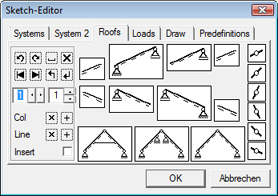 Rafters
:
Executed in the same way as with beams, the procedure goes from left to right. The left cantilever can also be inserted to the left if there is sufficient space. The roof pitch can be 30°, 45° and 60°.
Roofs: There are three roof systems available. These roof systems are always symmetrical but can however be supplemented by individual rafter sections. The roof width and the distance from the inferior purlin to the collar beam or to the
center purlin must be specified. The roof width must be a multiple of two and the distance to the interior purlin must be less than half the roof width.
Joints: There are joints on the right side as individual characters for the corresponding roof pitches. They are inserted at the cursor position.
Notes: The angle of these sections must be identical in order to connect rafters and roof members together. Please check the character direction. Not all dimensions are possible, especially at an angle of 30° due to the geometric conditions. The choice of dimension should be made via the controller or the mouse wheel. Only drawable values are recommended here.
"Loads" tab
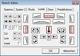 Triangular and area loads:
 The loads with vertical direction are always intelligently interconnected so that you are able to draw almost any load images. The loads in the horizontal direction are not interlinked.
Load arrows: The load arrows are defined by their direction and their length. The appropriate arrow must be selected. The character direction is
then inquired, which is not related to the direction of the arrowhead.
Moments: Moments are inserted as individual characters. Their size cannot be influenced.
"Draw" tab
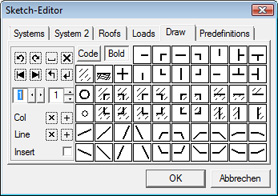
Elements for individual drawings are contained on this tab. It is possible to draw simple cross-sections or details with this collection.
Code button: You can select and draw individual characters from the three VCmaster fonts with this button. The character sets can be viewed by opening and, if necessary, printing the
ZeichenXVCmaster.pdf file in the VCmaster directory. Select the font and then the ASCII number accordingly.
Bold button: When the
Bold button is active, the characters are written in a heavier font.
This mode is activated either by pressing the
Bold button or on the display of the individual characters.
Notes: In
Bold mode, the characters have the same thickness as the beam, frame, support and roof elements. While drawing, the cursor can be positioned so that drawing can be continued. It is therefore possible to draw horizontal and vertical lines by repeatedly clicking on the relevant character.
Individual buttons:

Earth level can be indicated with this button.


Reinforcing bars can be shown with these buttons.
Predefinition tab
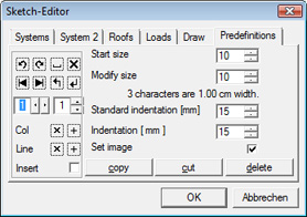 Start size:
 The start size is the font size that is preset if a new diagram is inserted.
Modify size: The font size of the current diagram can be changed here.
The actual impact of every modification is reflected directly in the
current VCmaster document. An approximate specification for enlarging the drawing can be found immediately below.
Standard indentation: Here you can define at which indent the graphic should be started.
Indentation: You can shift the current diagram in the document by indenting.
copy, cut, delete:
| copy |
Copy to clipboard |
| cut |
Copies and deletes |
| delete |
Deletes the current drawing |